Heat treatment of press brake tools

In order to improve its mechanical properties, tools need to undergo heat treatment such as quenching and hardening.

Quenching:

This is a type of heat treatment that includes heating and subsequent cooling of the steel to reduce internal stress in the material. During the heating process, martensite is generated, which has a very hard structure and high ultimate tensile strength, but low resilience.

Therefore, the material is prone to cracking; To avoid this issue, the steel is then tempered through controlled cooling. The cooling rate during tempering has a significant impact on the residual stress of the steel. The slower the cooling rate, the weaker the residual stress.

The steel grade that can undergo this treatment contains 0.4-0.6% carbon, hence it is called quenched and tempered steel.

Hardening:

The purpose of this treatment is to increase the hardness of the material, which includes heating the steel to a certain temperature and then rapid cooling.

The commonly used method for measuring tool hardness is the Rockwell hardness test, which is performed using a conical (HRC) or spherical (HRB) indenter.

It involves gradually increasing the load on the instrument. The hardness is determined by the depth of penetration of the indenter into the workpiece.

Induction hardening:

This is the most common heat treatment for press brake machine tools, but as it is a surface treatment, it only affects the outer layer of the tool.

This quenching utilizes the principle of electromagnetic induction: a conductive material (coil) is placed in a strong alternating magnetic field, the tool is heated to a high temperature, and then rapidly cooled by a flow of coolant.

Induction quenching can form a very hard surface with wear resistance and fatigue resistance, without affecting the toughness of the core.

Core hardening:

Some press brake machine tool manufacturers use core hardening to achieve consistent hardness throughout the tool, while the surface hardness value is low, and the surface is usually subject to wear.

Length and precision


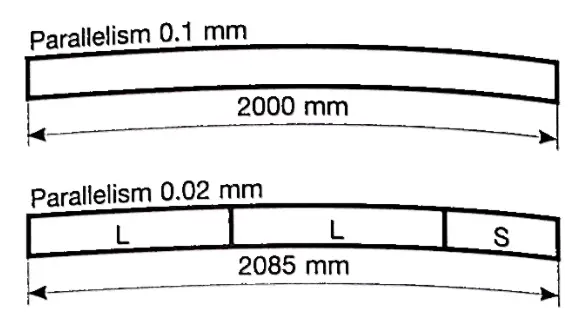
In the past, press brake machine tools were produced as single pieces, and their length was the same as that of the press brake machine or the profile to be bent. These steel tools are planed because hardening and grinding can cause them to deform due to their length. Due to the inability of the cutting tool to process, its accuracy is quite low, approximately 0.1 millimeters per meter.

With the emergence of new technologies, the accuracy of press brake machine tools has significantly improved. Today's tools are parts that are produced, hardened, and machined, ensuring higher accuracy (0.0 millimeters per pallet) and better mechanical performance than before. The length of the press brake machine tool varies depending on the type, for example, the Shinite tool has a length of 835mm.

The segmentation tool has several advantages: standard modular length, so that operators can purchase tools to form the required total length;

Easy to operate, saving time when installing the press brake machine;

Save costs because only worn or damaged parts of the tool need to be replaced, rather than the entire length;

The machine can be set up using different workstations and installation tools with different profiles that are used in sequence.

It is important that the tool dimensions are correct and can be fully interchangeable and aligned to utilize modern press brake machines and ensure high-quality press brake and repeatability.

Thanks to the surface finish generated by grinding machines, modern press brake machine tools can produce molds with radii in V-shaped molds and punch tips.

This allows for uniform press brake without marking the metal sheet and understanding the exact contact points between the tool and the metal sheet. This is important information for the CNC system of the press to automatically set press brake parameters to achieve maximum repeatability.

Press brake materials

What is the press brake mold made of?

There are many types of materials available for manufacturing press brake tools, including steel, alloy materials, polymer materials, etc.

At present, steel is the most widely used material for producing press brake molds, including T8 steel, T10 steel, 42CrMo, Cr12MoV, etc.

42CrMo is a high-strength alloy steel that exhibits high strength and toughness after quenching and tempering.

It can work at low temperatures as low as -500 ° C and is known for its high strength, toughness, and wear resistance.

The commonly used materials for press brake molds can be divided into eight categories.

1. Carbon tool steel

T8A and T10A carbon tool steels are often used in the manufacturing of press brake molds due to their excellent machinability and cost-effectiveness.

However, these materials have poor hardenability and red hardness, and significant deformation occurs during heat treatment. In addition, their load-bearing capacity is relatively low.

2. Low alloy tool steel

Adding an appropriate amount of alloying elements to carbon tool steel produces low alloy tool steel, reducing the tendency for deformation and cracking during quenching, and improving the hardenability and wear resistance of the steel.

Some low alloy steels commonly used in the production of press brake molds include CrWMn, 9Mn2V, 7CrSiMnMoV, and 6CrNiSiMnMoV.

3. High carbon and high chromium tool steel

High carbon and high chromium tool steel is famous for its excellent hardenability, toughness, and wear resistance.

During heat treatment, the deformation is minimal, making it a high wear-resistant steel with a load-bearing capacity second only to high-speed steel.

However, due to the obvious segregation of carbides, repeated upsetting and drawing (axial upsetting and radial drawing) are required to reduce the unevenness of carbides and improve their performance.

Some common high carbon and high chromium tool steels include Cr12, Cr12MoV, and Cr12MoV1.

4. High carbon medium chromium tool steel

High carbon medium chromium tool steel used for press brake molds includes Cr4W2MoV, Cr6W, Cr5MoV, etc.

These materials have low chromium content, fewer eutectic carbides, uniform distribution of carbides, minimal heat treatment deformation, good hardenability, and stable size.

Compared with high carbon steel and high chromium steel with obvious carbide segregation, these materials have improved properties.

5. High speed steel

High speed steel is commonly used in the production of press brake molds due to its high hardness, wear resistance, and compressive strength. It also has high load-bearing capacity.

Commonly used are W18Cr4V, W6Mo5, and Cr4V2 to reduce tungsten, as well as 6W6Mo5 and Cr4v high-speed steels developed to enhance toughness.

In order to improve the distribution of carbides, high-speed steel also needs to be forged.

6. Foundation steel

Basic steel is produced by adding a small amount of other elements to high-speed steel and adjusting its carbon content to enhance its performance.

Compared to high-speed steel, this can improve performance, such as increased wear resistance and hardness, as well as better fatigue strength and toughness.

It is a high-strength and high toughness bending die steel, which is more cost-effective than high-speed steel.

The commonly used basic steels for press brake molds include 6Cr4W3Mo2VNb, 7Cr7Mo2V2Si, 5Cr4Mo3SiMnVAL, etc.

7. Hard alloy and steel bonded hard alloy

Hard alloy has the highest hardness and wear resistance in bending die steel, but its strength and toughness during bending are poor.

Tungsten cobalt is used as a hard alloy in press brake molds.

For bending molds that require low impact and high wear resistance, hard alloys with low cobalt content can be selected. For high impact molds, hard alloys with high cobalt content can be used.

Steel bonded hard alloy is made by powder metallurgy using iron powder and a small amount of alloy element powder (such as chromium, molybdenum, tungsten, vanadium, etc.) as the binder, titanium carbide or tungsten carbide as the hard phase.

The matrix of steel bonded hard alloy is steel, which solves the problems of poor toughness and difficult processing of hard alloy.

This material can be cut, welded, forged, and heat treated. Steel bonded hard alloys contain many carbides, with lower hardness and wear resistance than hard alloys, but still higher than other steel grades.

After quenching and tempering, its hardness can reach 68-73HRC.

8. New materials

The material used for the press brake mold is a cold working mold steel, and its main performance requirements are strength, toughness, and wear resistance.

At present, the development trend of press brake mold steel mainly has two directions, both centered around high alloy steel D2 (Cr12MoV).

(1) Improving the toughness of bending molds, including reducing carbon content and alloy element content, and improving the uniformity of carbide distribution in steel. Examples in this direction include 8CrMo2V2Si and Cr8Mo2SiV.

(2) Improve the wear resistance of press brake molds and adapt to the high-speed, automated, and mass production of powder high-speed steel. An example of this direction is 320CrVMo13.

Press brake mold price

The cost of press brake molds usually depends on various factors, such as market conditions, customer psychology, competition, and manufacturer's situation.

The press brake mold manufacturer will conduct a comprehensive analysis of these factors to determine the cost of their punch and mold.

They may start with a base price that will increase by 10-30% to consider valuation, but this quotation can be negotiated and reduced based on specific circumstances. The final price shall be agreed upon by both parties and outlined in the contract.

It should be noted that the mold price may be higher or lower than the initial estimate, which only estimates the basic production cost and does not consider additional costs or profits.

It should be noted that the initial quotation for the press brake mold is not the final price, but only serves as an estimate of development costs.

After the product development is successful and profits are generated, the additional value of the mold fee is extracted as compensation to form the final mold price.

This price may be higher than the original estimate, and the return rate is also high, ranging from tens to hundreds of times the normal mold price. However, the return rate may also be zero.

For manufacturers, it is important to prioritize the quality, accuracy, and service life of press brake molds over cost. Pursuing low prices should not compromise the quality of high-tech products.

It is worth noting that due to factors such as equipment technology, personnel concepts, and consumption levels, mold valuation and prices vary among different enterprises, regions, and countries.

In more developed regions or larger and technologically advanced enterprises, the focus may be on high quality and high prices, while in regions with lower consumption levels or smaller enterprises, mold prices are expected to be lower.

It is also worth mentioning that mold prices will change over time, and the direct impact of mold prices may be poor.

Different time requirements and manufacturing cycles result in different mold prices. A pair of molds at different times have different prices, and molds with different manufacturing cycles have different prices.

Why does the CNC press brake need to add a compensation system

CNC press brake is an important equipment in sheet metal processing, and its working accuracy directly affects the bending accuracy of the workpiece. Why add a compensation system to the CNC press brake during the workpiece bending process, as the maximum force is exerted on both ends of the slider and the reaction force during sheet bending causes concave deformation on the lower surface of the slider.


Why does the CNC press brake need to add a compensation system


In order to eliminate the adverse effects of slider deformation, it is necessary to compensate for the deflection deformation of the slider. The usual compensation methods include hydraulic compensation and mechanical compensation, both of which generate upward elastic deformation in the middle of the Compensation workbench to offset the deformation of the machine tool slider, ensure the accuracy of the machining joint surface, and improve the accuracy of the workpiece. At present, major foreign machine tool manufacturers use mechanical compensation devices; Domestic manufacturers will choose appropriate compensation methods based on the actual situation.


Introduction to Two Compensation Methods


Hydraulic compensation method


The hydraulic automatic deflection compensation mechanism of the worktable is composed of a set of oil cylinders installed in the lower worktable. The position and size of each compensation cylinder are designed based on the deflection compensation curve of the slider and the finite element analysis of the worktable. Hydraulic compensation is achieved through the relative displacement between the front, middle, and rear three vertical plates to compensate for the protrusion of the neutral plate. Its principle is to achieve protrusion through the elastic deformation of the steel plate itself, So its compensation amount can be adjusted within the elastic range of the workbench.


Mechanical compensation method


Mechanical compensation is composed of a set of convex wedge blocks with inclined surfaces, each of which is designed based on the deflection curve of the slider and worktable finite element analysis. The CNC system calculates the required compensation amount based on the magnitude of the load force during the bending of the workpiece (which will cause deflection deformation of the slider and worktable vertical plate), automatically controls the relative movement of the protruding wedge block, and effectively compensates for the deflection deformation caused by the slider and worktable vertical plate. The ideal bending workpiece mechanical deflection compensation is achieved by controlling the position to achieve "pre protrusion", A set of wedges forms a curve in the length direction of the workbench that matches the actual deflection, ensuring that the gap between the upper and lower molds is consistent during bending, and ensuring that the angle of the bent workpiece in the length direction is consistent.


Comparison of Two Compensation Methods


The advantages of hydraulic compensation:


As time goes by, hydraulic compensation does not have any wear issues, while mechanical compensation screws, wedge-shaped blocks, etc. will experience wear over time.


Hydraulic compensation takes up less space, while mechanical compensation takes up more free space in both height and width directions.


When using hydraulic compensation, the plate cannot be displaced because the lower workbench is in contact with the ground of the bent plate as a whole, and the positioning of the stop finger is very stable when it contacts the "clamping point" of the plate horizontally. Mechanical compensation only takes effect after bending, and there is a possibility of unpredictable errors.


Hydraulic compensation can also be adjusted when the workpiece is not removed, which is impossible in mechanical compensation.


The advantages of mechanical compensation:


Mechanical compensation has long-lasting stability and reduces the difficulty and frequency of hydraulic compensation maintenance (such as oil leakage caused by seal ring damage), and is maintenance free during the service life of the machine tool.


Mechanical compensation, due to the large number of compensation points, can achieve precise deflection compensation throughout the entire length of the workbench, making it easier for the press brake to achieve linear compensation when bending workpieces during operation, and improving the bending effect of workpieces.


Mechanical compensation is the use of a potential ruler to measure the position of the return signal, which serves as a CNC axis to achieve digital control and make the compensation value more accurate.


Problems encountered when using CNC press brake


When we use the CNC press brake to work, there is a high possibility of some error problems. At this time, we need to pay attention and check immediately if there are any problems. The first step of inspection is to check if there is any wear or damage to the mold currently used by the press brake. If this is the cause of the error, then replace the mold.


However, during the inspection process, if no damage is found, the second step is to check the balance between the slider and the workbench. If the site cannot meet the usage requirements, adjustments must be made according to relevant standards to ensure that this parallelism can be maintained within the standard range.


If there is still a certain degree of error in the angle of the workpiece, it may not be due to the mold or parallelism, but it may be due to the hydraulic system of the equipment, where the balance mechanism does not ensure that the pressure oil evenly enters the left and right cylinders, and adjustment is needed.


At this point, it is necessary to adjust the working mode of the press brake to the "jog adjustment" state. Remove the mold or other accessories from the equipment, so that the slider can stay on the mechanical block. Then, adjust the pressure gauge correctly by compressing the dial gauge head of the press brake by 3-4 millimeters, stepping on the foot pedal to increase the system pressure. When the press brake system is pressurized or unloaded, Check the clockwise deviation of the dial gauge. If it reaches the specified value, the operation can be stopped. Of course, in addition to the above methods, it should be emphasized that the press brake must be well maintained to maximize its advantages in use.