What is the standard for tube sheets?

Tube sheets are commonly used industrial components, widely employed in industries such as chemical, petroleum, pharmaceuticals, and food processing. Tube sheet size standards refer to the standardized size specifications used in the design and manufacturing process to ensure interchangeability and universality of various pipeline equipment. This article provides a detailed introduction to tube sheet size standards.

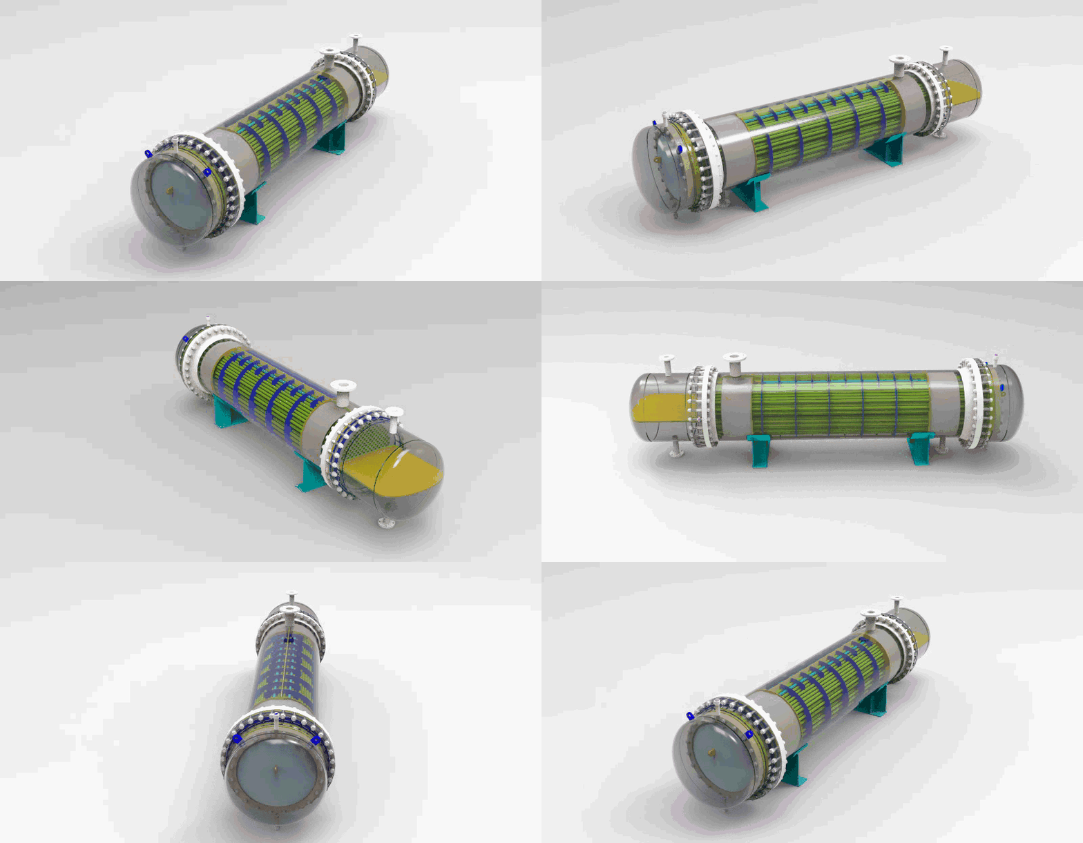
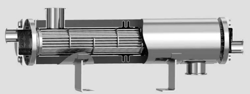
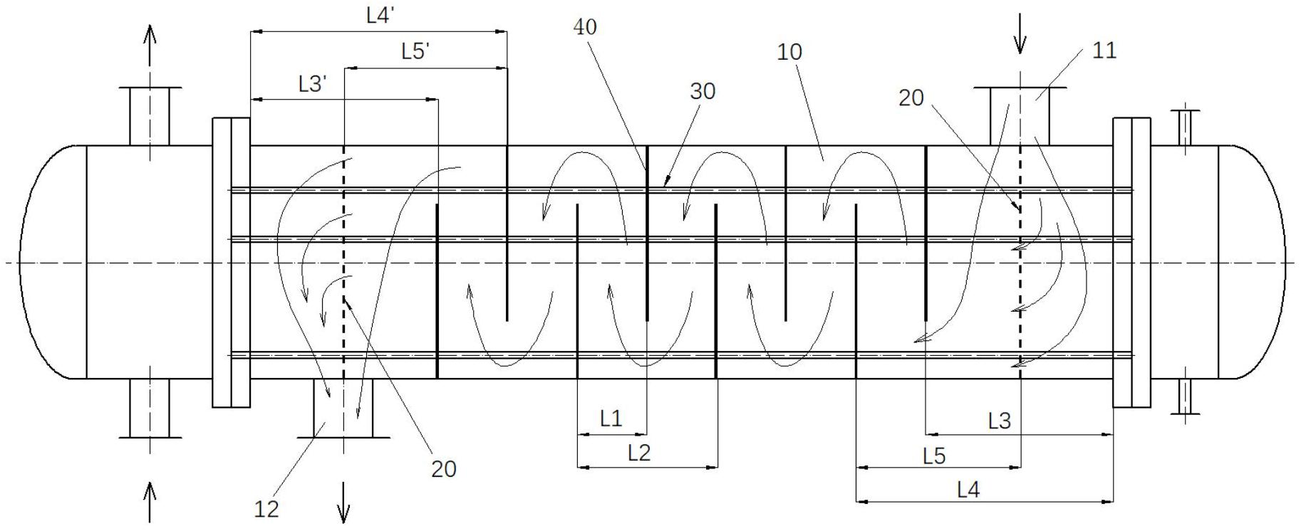
Tube Sheet Heat Exchanger


Tube Sheet Overview

1. Tube Sheet Definition

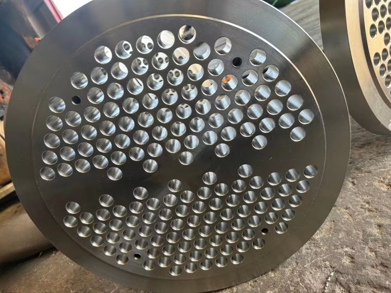
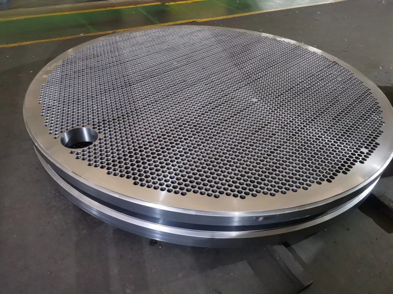
A tube sheet is a device that connects multiple pipelines or equipment and consists of two flat surfaces, typically with numerous holes on the top surface, with each hole connecting to one or more holes on the bottom surface.


2. Tube Sheet Classification

Depending on different application scenarios and functional requirements, tube sheets can be categorized into the following types:

(1) Distributors: Divert one inlet into two or more outlets.

(2) Collectors: Collect two or more inlets into one outlet.

(3) Heat Exchangers: Achieve heat exchange through the transfer of heat between internal fluids.

(4) Reactors: Complete chemical synthesis or other chemical processes through internal reactions.

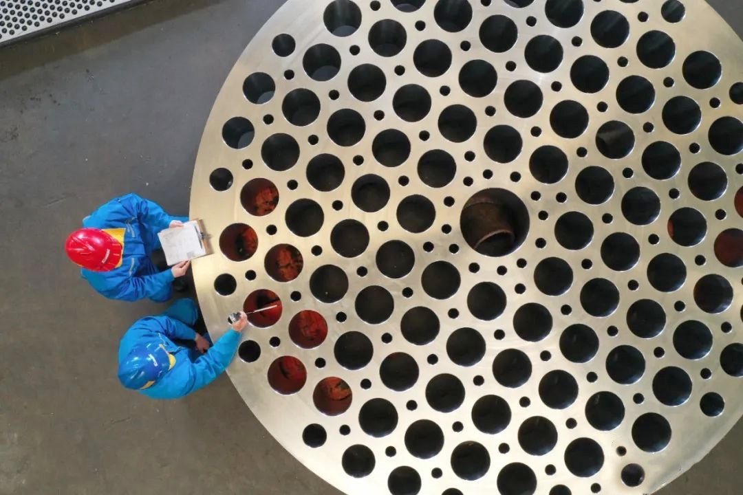
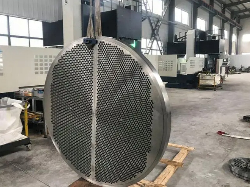
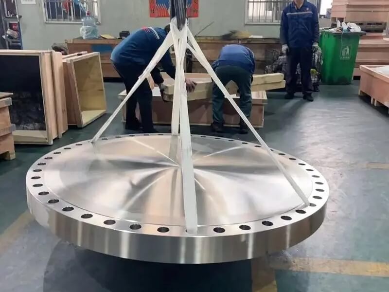
large tube sheet


Tube Sheet Size Standards

1. Tube Sheet Hole Diameter: In the design and manufacturing process, international standards like ISO/TR 10400 or ASME B16.5 are typically used as standard specifications for tube sheet hole diameters. Both of these standards specify a range of hole sizes, ranging from 1/2 inch to 48 inches.


2. Tube Sheet Thickness: Tube sheet thickness refers to the distance between the top and bottom surfaces of the tube sheet. In the design and manufacturing process, standards such as ASME B16.5 or GB/T 9119 are typically used as standard specifications for tube sheet thickness. These standards specify a range of thicknesses, ranging from 3 millimeters to 100 millimeters.


3. Tube Sheet Hole Spacing: Tube sheet hole spacing refers to the distance between adjacent holes. In the design and manufacturing process, standards like ASME B16.5 or GB/T 9119 are usually used as standard specifications for tube sheet hole spacing. These standards specify a range of hole spacing sizes, ranging from 15 millimeters to 600 millimeters.


4. Tube Sheet Material: Tube sheet material refers to the type and variety of materials used in manufacturing the tube sheet. In the design and manufacturing process, standards such as ASME B16.5, GB/T 9119, or JIS B2220 are typically used as standard specifications for tube sheet materials. These standards classify and specify various material types and varieties.Tube Sheet Heat Exchanger


Frequently Asked Questions


1. What is the purpose of tube sheet size standards?

The purpose of tube sheet size standards is to ensure the interchangeability and universality of various pipeline equipment, allowing pipeline equipment produced by different manufacturers to be compatible and work together.


2. What is the relationship between tube sheet hole diameter, thickness, and hole spacing?

There is no direct relationship between tube sheet hole diameter, thickness, and hole spacing. Different tube sheet size standards specify different ranges of hole diameter, thickness, and hole spacing sizes, and users can choose the appropriate specifications according to their needs.


3. What are the common types of tube sheet materials?

Common tube sheet materials include carbon steel, stainless steel, alloy steel, copper, aluminum, and more. Users can select the appropriate material type and variety based on their specific requirements.

 Tubesheet


Conclusion

Tube sheet size standards are crucial for ensuring the interchangeability and universality of various pipeline equipment and should be strictly followed during the design and manufacturing process. 


Wuxi Changrun has provided high-quality tube sheets, nozzles, flanges, and customized forgings for heat exchangers, boilers, pressure vessels, etc. to many well-known petrochemical enterprises at home and abroad. Our customers include PetroChina, Sinopec, Chevron, Bayer, Shell, BASF, etc. Send your drawings to sales@wuxichangrun.com We will provide you with the best quotation and the highest quality products.

fixed tube heat exchanger


Knowledge and calculation methods of forging ratio

Forging ratio is an indicator used to indicate the degree of metal deformation during the forging process, usually defined as the ratio of the cross-sectional area of the metal before and after forging.


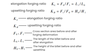
The calculation method for forging ratio can be the elongation forging ratio or the upsetting forging ratio. The elongation forging ratio refers to the ratio of the cross-sectional area of the steel ingot or billet before elongation to the cross-sectional area after elongation. The upsetting forging ratio, also known as the upsetting ratio or compression ratio, refers to the ratio of the cross-sectional area of the steel ingot or billet after upsetting to the cross-sectional area before upsetting. The selection of forging ratio is crucial for ensuring the quality and performance of forgings, and factors such as different metal materials, forging performance requirements, process types, and the shape and size of forgings need to be considered. For example, alloy structural steel ingots typically require a larger forging ratio, while electroslag steel ingots have better quality and require a smaller forging ratio.


The size of the forging ratio directly affects the mechanical properties and forging quality of the metal. Increasing the forging ratio is beneficial for improving the structure and properties of the metal, but excessive forging ratios may also lead to unnecessary waste and increased workload. Therefore, while ensuring the quality of forgings, it is advisable to choose a smaller forging ratio as much as possible.


1. Basic definition of forging ratio

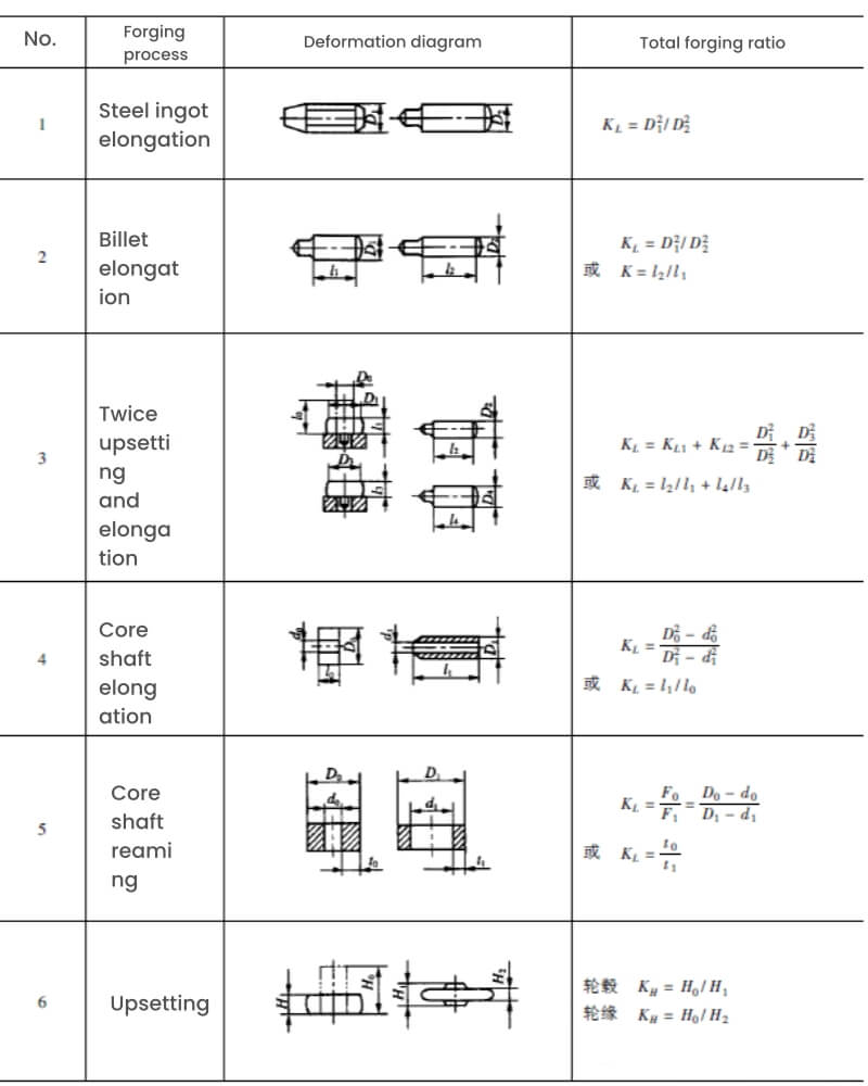
The ratio of the cross-sectional area of a metal billet before and after forging is called the forging ratio. It represents the magnitude of forging deformation, and the forging ratio can be calculated using the following formula:


2. Calculation methods of forging ratio

calculation methods of forging ratio

Note:

(1) The forging ratio of chamfered steel ingots is not included in the total forging ratio;

(2) When continuously elongating or upsetting, the total forging ratio is equal to the product of the sub forging ratios;

(3) When there is elongation between two upsets and when there is elongation between two upsets, the total forging ratio is equal to the sum of the two sub forging ratios, and it is required that each sub forging ratio is not less than 2.


About us:

Wuxi Changrun has provided high-quality tube sheets, nozzles, flanges, and customized forgings for heat exchangers, boilers, pressure vessels, etc. to many well-known petrochemical enterprises at home and abroad. Our customers include PetroChina, Sinopec, Chevron, Bayer, Shell, BASF, etc. Send your drawings to sales@wuxichangrun.com We will provide you with the best quotation and the highest quality products.


Our company has 27 international and domestic first-class brand drilling equipment that have been put into use, including 11 deep hole drills. We have advantages such as large processing specifications (maximum diameter of 8.6m), batch production, mature process plans, and standardized quality control. The processed tube sheet products are widely used in industries such as seawater desalination, heat exchangers, pressure vessels, paper machines, petroleum refining, steam turbines, and nuclear power.

Blind Flange

tube sheets


The difference between double tube sheet heat exchangers and single tube sheet heat exchangers

A double tube sheet heat exchanger is a heat exchanger with two tube sheets with a certain gap at one end of the heat exchanger.


At the end of the heat exchange tube, there is a tube sheet called the outer tube sheet, also known as the tube side tube sheet, which serves as an equipment flange and is connected to the heat exchange tube and channel flange. There is also a tube sheet located closer to the end of the heat exchange tube, called the inner tube sheet, which is the shell side tube sheet, connected to the heat exchange tube and the shell side.

There is a certain distance between the outer and inner tube sheets, and this space can be separated from the outside by a skirt segment, forming a pressure free isolation chamber; It can also be an open structure.


Application of double tube sheet heat exchanger

In practical operation, double tube sheet heat exchangers are generally used in the following two situations:

1.One is to absolutely prevent the mixing of media between the shell and tube sides, for example, in heat exchangers where water flows through the shell side or chlorine or chloride flows through the tube side. If the water in the shell side comes into contact with chlorine or chlorides in the tube side, it will produce highly corrosive hydrochloric acid or hypochlorous acid, which will cause serious corrosion to the material of the tube side.


Adopting a double tube sheet structure can effectively prevent the mixing of two materials, thereby preventing the occurrence of the above-mentioned accidents.


2.Another scenario is when there is a large pressure difference between the medium on the tube and shell side. In this case, a medium is usually added to the cavity between the inner and outer tube sheets to reduce the pressure difference between the medium on the tube and shell side.


When the mixing of heat exchanger tube side and shell side media is strictly prohibited in the following situations, a double tube sheet structure is often used:

① When the two media of the tube side and shell side are mixed, it will cause serious corrosion;

② The infiltration of extremely or highly hazardous media on one side into the other can cause serious consequences;

③ When the medium on the tube side and the medium on the shell side are mixed, the two media will cause combustion or explosion;

④ When one medium mixes with another, it causes catalyst poisoning;

⑤ Mixing the tube side and shell side media can cause polymerization or the formation of resin like substances;

⑥ The mixing of the tube side and shell side media can cause the termination or restriction of chemical reactions;

⑦ The mixing of tube side and shell side media can cause product contamination or a decrease in product quality.

double tube sheet heat exchanger


Comparison of double tube sheet and single tube sheet heat exchanger structures

The double tube sheet heat exchanger adopts a fixed tube sheet structure, and the tube bundle cannot be extracted for cleaning. The single tube sheet heat exchanger can adopt a variety of structural types, and the tube bundle can be extracted for cleaning. For double tube sheet heat exchangers with large temperature differences, corrugated expansion joints can be installed on the simplified structure; for single tube sheet heat exchangers, in addition to installing corrugated expansion joints on the simplified structure, floating heads or U-shaped tubes are often used to compensate.


There are two design concepts for double tube sheet heat exchangers: one believes that double tube sheet heat exchangers are used to absolutely prevent the mixing of media between the tube and shell sides. A drainage and backflow valve is designed to be installed on the cavity between the inner and outer tube sheets for daily observation and discharge in case of leakage of the inner tube plate, so that the medium on the tube and shell side is effectively isolated by the inner and outer layer tube sheets. This is the main purpose of using a double tube sheet structure.


Another view is that double tube sheet heat exchangers can be used in situations where the pressure difference between the tube and shell side media is large. A medium is designed to be added to the cavity between the inner and outer tube sheets to reduce the pressure difference between the tube and shell side media. This is similar to a typical single tube sheet heat exchanger, and it cannot be absolutely guaranteed that there will be no leakage from the pipe opening on the outer tube sheet.

single tube sheet heat exchanger


Comparison of the use of double tube sheet and single tube sheet heat exchangers

Single tube sheet heat exchangers are the most common. In addition to frequent leakage of gaskets, bolts, flanges, and joint seals during use, there may also be leakage of pipe openings on the tube sheet, as well as welding cracks. Most of the pipe mouth leaks on the single tube sheet heat exchanger occur at the welding arc end. During welding, the gas was not completely discharged and there were sand holes.


The double tube sheet heat exchanger has inner and outer double tube sheets, and if there is a leakage at the inner tube sheet and tube ends, there is also an outer tube sheet protection.


Welding cracks in single tube plate heat exchangers often occur at the joint between the flange and the shell of the heat exchanger. The main reason for the problem here is that the stress at the junction between the flange and the cylinder is high; The second is the sudden change in geometric size and shape, which makes it easy to bury defects.


The joint between the simplified large flange and the cylinder of the double tube sheet heat exchanger is located on the outer edge of the cavity formed between the inner and outer tube sheets, and there is no medium in the cavity or the medium pressure is very low. The stress condition is better than that of a single tube sheet heat exchanger.


In addition, the pressure test of the double tube plate heat exchanger needs to be conducted 4 times (tube side, shell side between two inner tube plates, and cavity between inner and outer tube plates on both sides), while the pressure test of the single tube plate heat exchanger needs to be conducted 2-3 times (tube side, shell side or tube side, shell side, and small float).


Comparison of Manufacturing Double Tube Sheet and Single Tube Sheet Heat Exchangers

① Costs

Compared with a single tube sheet heat exchanger, a double tube sheet heat exchanger adds two outer tube sheets, a cavity between the two inner and outer tube sheets, and heat exchange tubes in the cavity. At present, the price of double tube sheet heat exchangers ordered domestically is about 10-20% higher than that of single tube sheet heat exchangers ordered.

If the double tube sheet structure and single tube sheet structure are used as heat exchangers respectively, the weight of the double tube sheet is increased by 10% to 20% compared to the single tube sheet, and the cost is increased by 25% to 37%. Therefore, more attention should be paid to the manufacturing quality of double tube sheet heat exchangers, so that more money can be spent to achieve good results.


② Expansion joint

Usually, there are roughly four forms of connection between heat exchange tubes and tube sheets, namely strength welding (commonly argon arc welding), strength expansion, strength welding+adhesive expansion, and strength expansion+sealing welding. The differences are mainly reflected in whether the tube holes are slotted, the welding groove, and the length of the tube extension. Expansion joints can be divided into non-uniform expansion joints (mechanical ball expansion joints), uniform expansion joints (hydraulic expansion joints, liquid bag expansion joints, rubber expansion joints, explosive expansion joints, etc.).


The design of the double tube sheet heat exchanger requires strength welding and strength expansion, and it is recommended to use the hydraulic expansion method. The general design requirement for single tube sheet heat exchangers is to use strength welding and adhesive expansion, and mechanical or manual expansion can be used.


At present, most domestic manufacturers do not have hydraulic expansion equipment. Even if they do, due to the high cost of purchasing hydraulic expansion heads and high losses (with an average expansion of over 100 pipe openings, a new hydraulic expansion head is required). Hydraulic expansion head is disposable and cannot be repaired.


Therefore, hydraulic expansion tube method is rarely used to manufacture heat exchangers.


Wuxi Changrun has provided high-quality tube sheets, nozzles, flanges, and customized forgings for heat exchangers, boilers, pressure vessels, etc. to many well-known petrochemical enterprises at home and abroad. Our customers include PetroChina, Sinopec, Chevron, Bayer, Shell, BASF, etc. Send your drawings to sales@wuxichangrun.com We will provide you with the best quotation and the highest quality products.


tube sheet

What should you pay attention to when using low-temperature pressure vessels?

Structural design

The structural design of low-temperature pressure vessels should consider sufficient flexibility, and the main requirements are as follows:

① The structure should be as simple as possible to reduce the constraints between welded components;

② Structural design should avoid generating excessive temperature gradients;

③ Sharp changes in the cross-section should be avoided as much as possible to reduce local stress concentration. The inner end of the plug-in nozzle should be polished into a rounded corner to ensure a smooth transition;

④ The connection welds of attachments should not be discontinuous or spot welded;

⑤ The saddle, manifold lug, support leg (excluding spherical tanks) or skirt of the container should be equipped with a pad or connecting plate to avoid direct welding with the container shell. The pad or connecting plate should be considered based on low-temperature materials;

⑥ The reinforcement of takeover should be carried out as much as possible using integral reinforcement or thick walled pipe reinforcement. If reinforcement pads are used, the weld seam should have a smooth transition;

⑦ For containers that cannot undergo overall heat treatment, if the welded components need to be stress relieved, consideration should be given to the individual heat treatment of the components.


Opening for connecting pipes

The opening of the connecting pipe for low-temperature pressure vessels should be avoided as much as possible from the main weld seam and its surrounding area. If it is necessary to open a hole in the weld seam area, it should comply with the requirements of relevant standards.

The connecting pipes on low-temperature pressure vessels should meet the following requirements:

① The wall thickness of the section welded to the shell should not be less than 5mm. For pipes with a diameter of DN ≤ 50mm, thick walled pipes should be used, and the extended part should be made of ordinary seamless steel pipes with a wall thickness;

② Bends made by simmering or pressing should be used at bends, and straight pipe welding (shrimp elbows) should not be used;

③ For plug-in nozzles, the sharp corners of the inner pipe end of the shell wall need to be turned or polished to a rounded corner of R ≥ 3mm;

④ The longitudinal weld seam and the circumferential weld seam between pipe sections when using coiled pipes for takeover should adopt a fully welded structure;

⑤ For hazardous media that are extremely flammable or highly toxic, or when the pressure is ≥ 1.6 MPa, The T-shaped joint should adopt a seamless extruded tee or a structure with thickened pipe openings and welding.
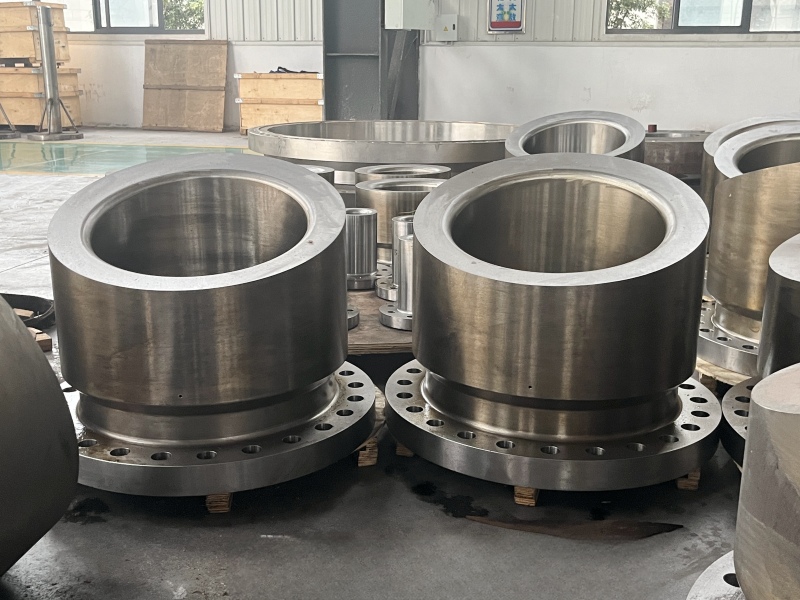
Forged Nozzle


Flange

Butt welded flanges should be used for flanges that meet the following conditions:

① Container flanges with a design pressure of ≥ 1.60MPa and containing highly flammable or toxic media, or connecting flanges with significant external loads;

② Vessel flanges and connecting flanges with a design pressure of ≥ 2.50MPa.

Butt welded flanges should be produced using seamless forging or rolling processes, and it is not allowed to use thick steel plates for cutting; It is allowed to use structural steel or steel plates bent or welded, but post weld heat treatment is required. If steel plate bending is used, the steel plate should be cut into strips along the rolling direction. When bending, the surface of the steel plate should be parallel to the centerline of the flange, and ultrasonic testing must also be performed on the steel plate.
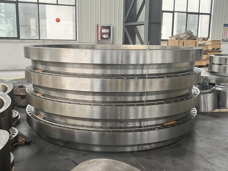
pressure vessel flange


Fasteners

The main requirements are as follows:

①The bolts, stud, and other fasteners used for flanges of low-temperature pressure vessels shall not use general ferrite commodity fasteners matched with nuts. General commodity nuts are allowed to be used, but the operating temperature should not be lower than -40 ℃;

② Recommend using elastic bolts and studs with a core diameter not exceeding 0.9 times the thread root diameter and no thread in the middle;

③ For ferritic steel vessels with a design temperature not lower than -100 ℃, ferritic steel fasteners (studs, bolts, nuts, washers) should be used. For austenitic steel vessels with a design temperature lower than -100 ℃, austenitic steel fasteners should be used;

④ A2 grade austenitic steel commercial fasteners in accordance with GB 3098.6 "Mechanical Properties of Fasteners - Stainless Steel Bolts, Screws, and Studs" can be used in low-temperature pressure vessels not lower than -196 ℃;

⑤ For stress reducing conditions, when the adjusted impact test temperature is equal to or higher than -20 ℃, general ferrite commodity fasteners can be used.
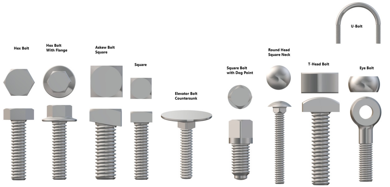
bolt stud nut


Sealing gasket

The commonly used sealing gaskets for low-temperature pressure vessels include gaskets made of metal materials (including semi metal gaskets) and non-metallic materials. The conditions and requirements are as follows.

① Metal materials used for sealing gaskets with temperatures below -40 ℃ should be austenitic stainless steel, copper, aluminum, and other metal materials that have no obvious transformation characteristics at low temperatures, including the metal strip of spiral wound gaskets, the shell of metal wrapped gaskets, and hollow or solid metal gaskets.

② Non metallic sealing gaskets should be made of materials that exhibit good elasticity at low temperatures, such as asbestos, flexible (expanded) graphite, polytetrafluoroethylene, etc. The usage conditions are as follows:

The flange sealing gasket with a temperature not lower than -40 ℃ and a pressure not higher than 2.5MPa is allowed to use high-quality asbestos rubber sheets, asbestos free rubber sheets, flexible (expanded) graphite sheets, polyethylene sheets, etc; High quality asbestos rubber sheets soaked in paraffin are allowed for flange gaskets with a temperature not lower than -120 ℃ and a pressure not higher than 1.6MPa.
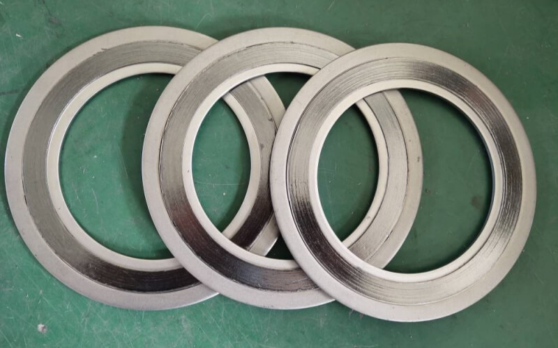
spiral wound gasket


Welding

The main requirements are as follows.

① For A B. All C-class welds should adopt a fully penetrated structure. For Class D welds, except for the welding between the flange and the container wall, the welding between small diameter nozzles (DN ≤ 50mm) and thicker heads or cover plates, and the connection between pipe joints with internal threads and the container wall, which can be in accordance with the relevant provisions of HG 20582, full penetration structures should also be used.

② Before welding low-temperature pressure vessels, welding process evaluation should be carried out, with a focus on the low-temperature Charpy (V-notch) impact test of the weld seam and heat affected zone. The qualification index should be determined according to the requirements of the base material and should not be lower than the performance of the base material.

③ During the welding process, the welding wire energy should be strictly controlled within the range specified in the process evaluation. It is advisable to choose a smaller welding wire energy for multi pass welding.

④ The butt weld must be fully welded, and the excess height of the weld should be minimized as much as possible, not exceeding 10% of the thickness of the welded part, and not exceeding 3mm. The fillet weld should be smooth and not allowed to protrude outward. The surface of the weld seam should not have defects such as cracks, pores, and undercuts, and there should be no sharp shape changes. All transitions should be smooth.

⑤ Arc ignition is not allowed in non welding areas. Arc ignition should be carried out using arc plates or within the groove.

⑥ Welding attachments, fixtures, braces, etc. must use the same welding materials and welding processes as the shell material, and be welded by qualified formal welders. The length of the weld bead must not be less than 50mm.

⑦ Surface damage to containers caused by mechanical processing, welding, or assembly, such as scratches, welding scars, arc pits, and other defects, should be repaired and ground. The wall thickness after grinding shall not be less than the calculated thickness of the container plus corrosion allowance, and the grinding depth shall not exceed 5% of the nominal thickness of the container and shall not exceed 2mm.

⑧ Discontinuous or spot welded joints are not allowed.


Wuxi Changrun has provided high-quality tube sheets, nozzles, flanges, and customized forgings for heat exchangers, boilers, pressure vessels, etc. to many well-known petrochemical enterprises at home and abroad. Our customers include PetroChina, Sinopec, Chevron, Bayer, Shell, BASF, etc. Send your drawings to sales@wuxichangrun.com We will provide you with the best quotation and the highest quality products.