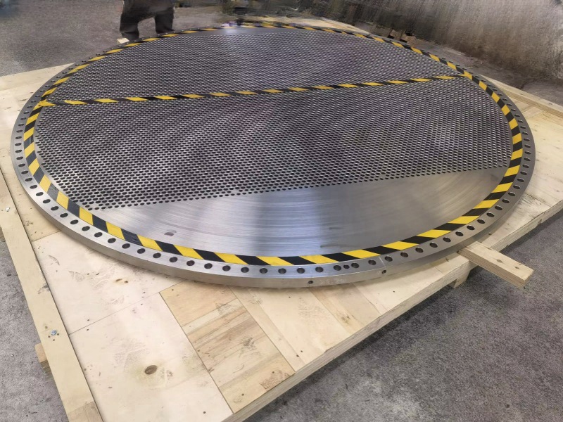
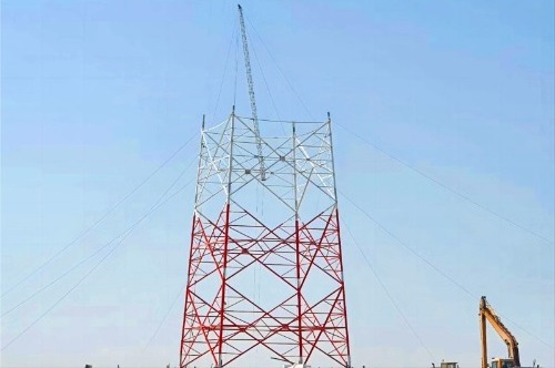
The difference between double tube sheet heat exchangers and single tube sheet heat exchangers

A double tube sheet heat exchanger is a heat exchanger with two tube sheets with a certain gap at one end of the heat exchanger.


At the end of the heat exchange tube, there is a tube sheet called the outer tube sheet, also known as the tube side tube sheet, which serves as an equipment flange and is connected to the heat exchange tube and channel flange. There is also a tube sheet located closer to the end of the heat exchange tube, called the inner tube sheet, which is the shell side tube sheet, connected to the heat exchange tube and the shell side.

There is a certain distance between the outer and inner tube sheets, and this space can be separated from the outside by a skirt segment, forming a pressure free isolation chamber; It can also be an open structure.


Application of double tube sheet heat exchanger

In practical operation, double tube sheet heat exchangers are generally used in the following two situations:

1.One is to absolutely prevent the mixing of media between the shell and tube sides, for example, in heat exchangers where water flows through the shell side or chlorine or chloride flows through the tube side. If the water in the shell side comes into contact with chlorine or chlorides in the tube side, it will produce highly corrosive hydrochloric acid or hypochlorous acid, which will cause serious corrosion to the material of the tube side.


Adopting a double tube sheet structure can effectively prevent the mixing of two materials, thereby preventing the occurrence of the above-mentioned accidents.


2.Another scenario is when there is a large pressure difference between the medium on the tube and shell side. In this case, a medium is usually added to the cavity between the inner and outer tube sheets to reduce the pressure difference between the medium on the tube and shell side.


When the mixing of heat exchanger tube side and shell side media is strictly prohibited in the following situations, a double tube sheet structure is often used:

① When the two media of the tube side and shell side are mixed, it will cause serious corrosion;

② The infiltration of extremely or highly hazardous media on one side into the other can cause serious consequences;

③ When the medium on the tube side and the medium on the shell side are mixed, the two media will cause combustion or explosion;

④ When one medium mixes with another, it causes catalyst poisoning;

⑤ Mixing the tube side and shell side media can cause polymerization or the formation of resin like substances;

⑥ The mixing of the tube side and shell side media can cause the termination or restriction of chemical reactions;

⑦ The mixing of tube side and shell side media can cause product contamination or a decrease in product quality.
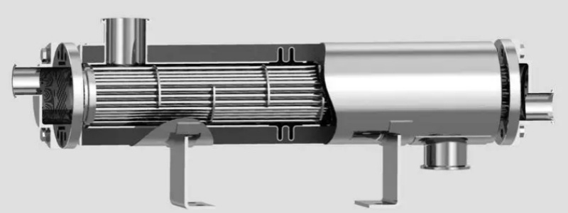
double tube sheet heat exchanger


Comparison of double tube sheet and single tube sheet heat exchanger structures

The double tube sheet heat exchanger adopts a fixed tube sheet structure, and the tube bundle cannot be extracted for cleaning. The single tube sheet heat exchanger can adopt a variety of structural types, and the tube bundle can be extracted for cleaning. For double tube sheet heat exchangers with large temperature differences, corrugated expansion joints can be installed on the simplified structure; for single tube sheet heat exchangers, in addition to installing corrugated expansion joints on the simplified structure, floating heads or U-shaped tubes are often used to compensate.


There are two design concepts for double tube sheet heat exchangers: one believes that double tube sheet heat exchangers are used to absolutely prevent the mixing of media between the tube and shell sides. A drainage and backflow valve is designed to be installed on the cavity between the inner and outer tube sheets for daily observation and discharge in case of leakage of the inner tube plate, so that the medium on the tube and shell side is effectively isolated by the inner and outer layer tube sheets. This is the main purpose of using a double tube sheet structure.


Another view is that double tube sheet heat exchangers can be used in situations where the pressure difference between the tube and shell side media is large. A medium is designed to be added to the cavity between the inner and outer tube sheets to reduce the pressure difference between the tube and shell side media. This is similar to a typical single tube sheet heat exchanger, and it cannot be absolutely guaranteed that there will be no leakage from the pipe opening on the outer tube sheet.
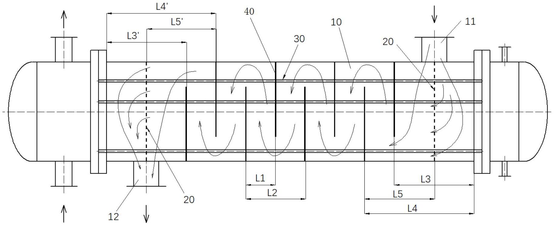
single tube sheet heat exchanger


Comparison of the use of double tube sheet and single tube sheet heat exchangers

Single tube sheet heat exchangers are the most common. In addition to frequent leakage of gaskets, bolts, flanges, and joint seals during use, there may also be leakage of pipe openings on the tube sheet, as well as welding cracks. Most of the pipe mouth leaks on the single tube sheet heat exchanger occur at the welding arc end. During welding, the gas was not completely discharged and there were sand holes.


The double tube sheet heat exchanger has inner and outer double tube sheets, and if there is a leakage at the inner tube sheet and tube ends, there is also an outer tube sheet protection.


Welding cracks in single tube plate heat exchangers often occur at the joint between the flange and the shell of the heat exchanger. The main reason for the problem here is that the stress at the junction between the flange and the cylinder is high; The second is the sudden change in geometric size and shape, which makes it easy to bury defects.


The joint between the simplified large flange and the cylinder of the double tube sheet heat exchanger is located on the outer edge of the cavity formed between the inner and outer tube sheets, and there is no medium in the cavity or the medium pressure is very low. The stress condition is better than that of a single tube sheet heat exchanger.


In addition, the pressure test of the double tube plate heat exchanger needs to be conducted 4 times (tube side, shell side between two inner tube plates, and cavity between inner and outer tube plates on both sides), while the pressure test of the single tube plate heat exchanger needs to be conducted 2-3 times (tube side, shell side or tube side, shell side, and small float).


Comparison of Manufacturing Double Tube Sheet and Single Tube Sheet Heat Exchangers

① Costs

Compared with a single tube sheet heat exchanger, a double tube sheet heat exchanger adds two outer tube sheets, a cavity between the two inner and outer tube sheets, and heat exchange tubes in the cavity. At present, the price of double tube sheet heat exchangers ordered domestically is about 10-20% higher than that of single tube sheet heat exchangers ordered.

If the double tube sheet structure and single tube sheet structure are used as heat exchangers respectively, the weight of the double tube sheet is increased by 10% to 20% compared to the single tube sheet, and the cost is increased by 25% to 37%. Therefore, more attention should be paid to the manufacturing quality of double tube sheet heat exchangers, so that more money can be spent to achieve good results.


② Expansion joint

Usually, there are roughly four forms of connection between heat exchange tubes and tube sheets, namely strength welding (commonly argon arc welding), strength expansion, strength welding+adhesive expansion, and strength expansion+sealing welding. The differences are mainly reflected in whether the tube holes are slotted, the welding groove, and the length of the tube extension. Expansion joints can be divided into non-uniform expansion joints (mechanical ball expansion joints), uniform expansion joints (hydraulic expansion joints, liquid bag expansion joints, rubber expansion joints, explosive expansion joints, etc.).


The design of the double tube sheet heat exchanger requires strength welding and strength expansion, and it is recommended to use the hydraulic expansion method. The general design requirement for single tube sheet heat exchangers is to use strength welding and adhesive expansion, and mechanical or manual expansion can be used.


At present, most domestic manufacturers do not have hydraulic expansion equipment. Even if they do, due to the high cost of purchasing hydraulic expansion heads and high losses (with an average expansion of over 100 pipe openings, a new hydraulic expansion head is required). Hydraulic expansion head is disposable and cannot be repaired.


Therefore, hydraulic expansion tube method is rarely used to manufacture heat exchangers.


Wuxi Changrun has provided high-quality tube sheets, nozzles, flanges, and customized forgings for heat exchangers, boilers, pressure vessels, etc. to many well-known petrochemical enterprises at home and abroad. Our customers include PetroChina, Sinopec, Chevron, Bayer, Shell, BASF, etc. Send your drawings to sales@wuxichangrun.com We will provide you with the best quotation and the highest quality products.
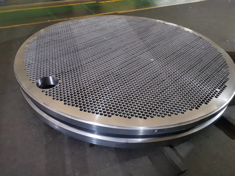
 

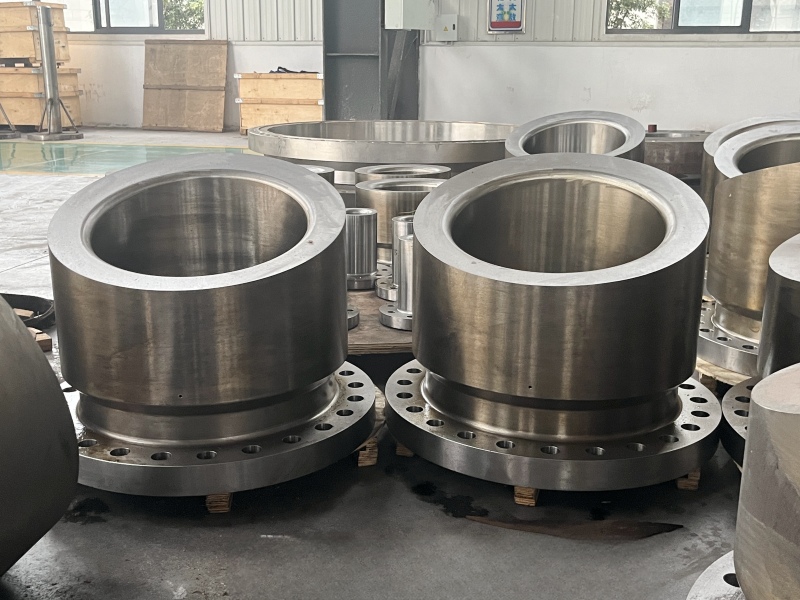
tube sheet

The Testing methods of tube sheet

What are the tube sheet inspection and testing methods?

Tube sheet inspection and testing methods are used to ensure the integrity and safety of tube sheets, which are components used in heat exchangers and other types of equipment. There are several methods used for tube sheet inspection and testing, including:


Visual Inspection

This is the simplest method of tube sheet inspection, which involves a visual examination of the tube sheet surface for any visible cracks, corrosion, erosion or other signs of damage.


Dye Penetrant Test (PT)

This method involves applying a dye penetrant to the surface of the tube sheet and then wiping off the excess. The penetrant is then drawn into any cracks or other surface defects by capillary action. A developer is applied, which draws the penetrant out of the cracks and makes them visible.


Magnetic Particle Test (MT)

This method involves applying a magnetic field to the tube sheet and then applying ferromagnetic particles to the surface. Any surface cracks or defects will cause the magnetic field to be distorted, making the particles cluster at the location of the defect, which can then be visually detected.


Ultrasonic Testing (UT)

This method uses high-frequency sound waves to detect defects in the tube sheet. A probe is placed on the surface of the tube sheet, which emits sound waves that travel through the material. Any defects in the material will cause some of the sound waves to be reflected back to the probe, which can be detected and analyzed.


Eddy Current Testing (ECT)

This method involves passing an alternating electrical current through a coil, which induces eddy currents in the tube sheet. Any defects in the material will cause changes in the eddy currents, which can be detected and analyzed.


These methods can be used individually or in combination to provide a comprehensive inspection and testing of tube sheets. The choice of method(s) used will depend on the type of equipment, the material of the tube sheet, and the level of sensitivity required for defect detection.


Wuxi Changrun has provided high-quality tube sheets, nozzles, flanges, and customized forgings for heat exchangers, boilers, pressure vessels, etc. to many well-known petrochemical enterprises at home and abroad. Our customers include PetroChina, Sinopec, Chevron, Bayer, Shell, BASF, etc. Send your drawings to sales@wuxichangrun.com We will provide you with the best quotation and the highest quality products.
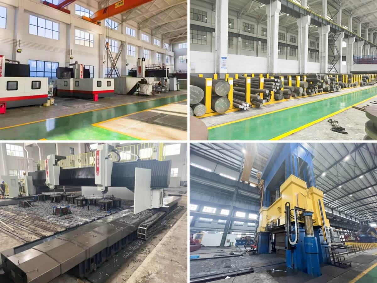
 

tube sheet processing


tube sheet workshop

Theoretical basis for tube sheet calculation

1. Theoretical basis for tube sheet calculation


The structure of shell and tube heat exchangers is complex, and there are many factors that affect the strength of the tube sheet. In particular, the tube sheet of fixed tube sheet heat exchangers is subjected to the most complex force. The design specifications of various countries basically consider the tube sheet as a circular flat plate that bears uniformly distributed loads, is placed on an elastic foundation, and is uniformly weakened by the tube holes (Figure 1).


Due to the many factors that affect the strength of the tube sheet, it is difficult and complex to accurately analyze the strength of the tube sheet. Therefore, various countries simplify and assume the formula for calculating the thickness of the tube sheet to obtain an approximate formula.


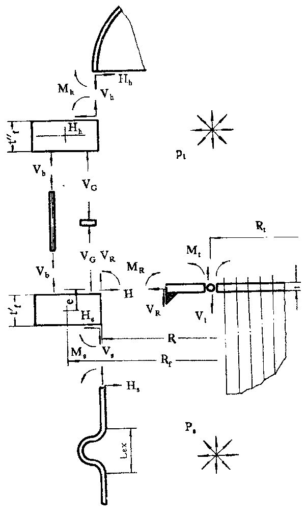
The loads that cause stress on the tube sheet include pressure (tube side pressure Pt, shell side pressure Ps), thermal expansion difference between the tube and shell, and flange torque. The mechanical model of the calculation method for the tube sheet of the heat exchanger is shown in Figure 2.


1.1 The design specifications of various countries consider the following factors to varying degrees for the tube sheets:

1) Simplifying the actual tube sheet into a homogeneous equivalent circular flat plate based on equivalent elasticity weakened by regular arrangement of tube holes and reinforced by tubes has been adopted by most countries' tube plate specifications today.

2) The narrow non piping area around the tube sheet is simplified as a circular solid plate based on its area.

3) The edge of the tube sheet can have various types of connection structures, which may include shell side cylinders, channel cylinders, flanges, bolts, gaskets, and other components. Calculate according to the actual elastic constraint conditions of each component on the edge of the tube sheet.

4) Consider the effect of flange torque on the tube sheet.

5) Consider the temperature difference stress caused by the thermal expansion difference between the heat exchange tube and the shell side cylinder, as well as the temperature stress caused by the temperature difference at various points on the tube sheet.

6)Calculate various equivalent elastic constants and strength parameters converted from porous plates with heat exchange tubes to equivalent solid plates.


1.2 Theoretical basis for GB151 tube sheet calculation

The mechanical model considers the tube plate as an axial symmetry structure and assumes that the tubesheets at both ends of the heat exchanger have the same material and thickness. For fixed tube sheet heat exchangers, the two tube sheets should also have the same boundary support conditions.


1) The supporting effect of tube bundle on tube sheet

Consider the tube sheet as an equivalent circular flat plate uniformly weakened and placed on an elastic foundation. This is because in the structure of shell and tube heat exchangers, the diameter of the majority of tubes is relatively small compared to the diameter of the tube sheet, and the number of tubes is sufficient. It is assumed that they are uniformly distributed on the tube sheet, so the support effect of each discrete heat exchange tube on the tube sheet can be considered uniform and continuous, and the load borne by the tube sheet is also considered uniformly distributed.


The tube bundle has a restraining effect on the deflection and rotation angle of the tube sheet under external loads. The restraining effect of the tube bundle can reduce the deflection of the tube sheet and lower the stress in the tube sheet. The tube bundle has a restraining effect on the angle of the tube sheet. Through analysis and calculation of actual parameters, it was found that the restraining effect of the tube bundle on the angle of the tube sheet has a very small impact on the strength of the tube sheet and can be completely ignored. Therefore, this


The specification does not consider the constraint effect of tube bundles on the corner of the tube sheet, but only considers the constraint effect of tube bundles on the deflection of the tube sheet. For fixed tube sheet heat exchangers, the tube reinforcement coefficient K is used to represent the tube sheet.


The bending stiffness of the perforated tube plate is η D

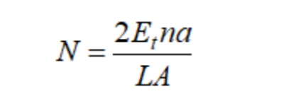
The elastic foundation coefficient N of the tube bundle represents the pressure load required to be applied on the surface of the tube plate to cause unit length deformation (elongation or shortening) of the tube bundle in the axial direction.


the pipe reinforcement coefficient K and substitute it into the expressions D and N, so that ν P=0.3:

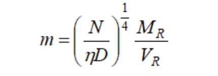
This coefficient indicates the strength of the elastic foundation relative to the tube plate's inherent bending stiffness, reflecting the enhanced load-bearing capacity of the tube bundle on the plate. It is a crucial parameter that characterizes the strengthening effect of the tube bundle on the plate. If the elastic foundation of the plate is weak, the enhancing effect of the heat exchange tubes is minimal, resulting in a small K value. Consequently, the plate's deflection and bending moment distribution resemble those of ordinary circular plates lacking an elastic foundation. Specifically, when K equals zero, the plate becomes an ordinary circular plate. Based on the theory of elastic foundation circular plates, the plate's deflection is not solely determined by the tube's strengthening coefficient K, but also by its peripheral support and additional loads, quantitatively represented by the total bending moment coefficient m.


When the periphery of the tube sheet is simply supported, MR=0, then m=0; When the periphery of the tube sheet is fixed, the corner of the edge of the tube sheet φ R=0, from which a specific value of m can be obtained (the expression is omitted); When the periphery of the tube plate only bears the action of bending moment, i.e. VR=0, then m=∞.

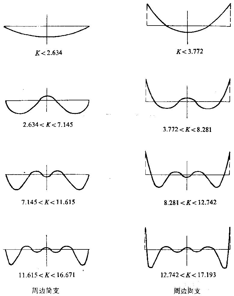
Under certain boundary support conditions, as the K value gradually increases, the deflection and bending moment of the tubesheet exhibit a attenuation and wavy distribution from the periphery to the center. The larger the K value, the faster the attenuation and the more wave numbers. During the process of increasing K value, when passing through a certain boundary K value, new waves will appear in the distribution curve. At the center of the plate, the curve changes from concave (or concave) to concave (or concave). Solving the derivative equation of the distribution curve can obtain the K boundary value of the curve with an increase in wave number.


Taking the simple support around the tube sheet as an example, as the strengthening coefficient K of the tube increases, the radial bending moment distribution curve and the boundary K value when new waves appear are shown in Figure 31. At the same time, it can be seen that the radial extreme value also moves away from the center of the tube sheet towards the periphery as the K value increases.


For the elastic foundation plate with peripheral fixed support, the radial bending moment distribution shows a similar trend with the change of K value, as shown in Figure 3. The difference from a simply supported boundary is that the maximum radial bending moment of the elastic foundation plate supported by a fixed boundary is always located around the circular plate, while the extreme point of the second radial bending moment moves away from the center of the plate and towards the periphery as K increases.


For floating head and filled box heat exchanger tube sheets, the modulus K of the tube bundle is similar to the elastic foundation coefficient N of the fixed tube sheet, which also reflects the strengthening effect of the tube bundle as an elastic foundation on the tube sheet.


2) The weakening effect of tube holes on tube sheets

The tube sheet is densely covered with dispersed tube holes, so the tube holes have a weakening effect on the tube sheet. The weakening effect of tube holes on the tube sheet has two aspects:


The overall weakening effect on the tube sheet reduces both the stiffness and strength of the tube sheet, and there is local stress concentration at the edge of the tube hole, only considering peak stress.


This specification only considers the weakening effect of openings on the overall tube sheet, calculates the average equivalent stress as the basic design stress, that is, approximately considers the tube sheet as a uniformly and continuously weakened equivalent circular flat plate. For local stress concentration at the edge of the tube hole, only peak stress is considered. But it should be considered in fatigue design.


The tube hole has a weakening effect on the tube sheet, but also considers the strengthening effect of the pipe wall, so the stiffness weakening coefficient is used η And strength weakening coefficient μ。 According to elastic theory analysis and experiments, this specification stipulates η and μ= 0.4.


3) Equivalent diameter of tube sheet layout area

The calculation of the reinforcement coefficient for fixed tube sheets assumes that all pipes are uniformly distributed within the diameter range of the cylinder. In fact, under normal circumstances, there is a narrow non pipe area around the tube sheet, which reduces the stress at the edge of the tube sheet.


The tube layout area is generally an irregular polygon, and now the equivalent circular pipe layout area is used instead of the polygonal pipe layout area. The value of the equivalent diameter Dt should make the supporting area of the tube on the tube sheet equal. The diameter size directly affects the stress magnitude and distribution of the tube plate. In the stress calculation of the fixed tube sheet in GB151, the stress located at the junction of the annular plate and the pipe layout area is approximately taken as the stress of the full pipe layout tube plate at a radius of Dt/2. Therefore, the standard limits this calculation method to only be applicable to situations where the non pipe layout area around the tube plate is narrow, that is, when the non dimensional width k of the non pipe layout area around the tube sheet is small, k=K (1)- ρ t) ≤ 1.


Whether it is a fixed tube sheet heat exchanger, or a floating head or filled box heat exchanger, when calculating the area of the tube layout area, it is assumed that the tubes are uniformly covered within the range of the tube layout area.


Assuming there are n heat exchange tubes with a spacing of S. For a triangular arrangement of tube holes, the supporting effect of each tube on the tube sheet is the hexagonal area centered on the center of the tube hole and with S as its inner tangent diameter, i.e;


For tubes with square arrangement of tube holes, the supporting area of each tube on the tube sheet is a square area centered on the center of the tube hole and with S as the side length, i.e. S2.


The tube sheet layout area is the area enclosed by connecting the supporting area of the outermost tube of the tube sheet, including the supporting area of the outermost tube itself.


For a single pass heat exchanger tube sheet with uniformly distributed heat exchange tubes, the supporting area of all n heat exchange tubes on the tube sheet is the area of the tube layout area.


4) Consider the bending effect of the tube sheet, as well as the tensile effect of the tube sheet and flange along their central plane.


5) Assuming that when the flange deforms, the shape of its cross-section remains unchanged, but only the rotation and radial displacement of the center of gravity around the ring section. Due to this rotation and radial displacement, the radial displacement at the connection point between the flange and the center surface of the tube sheet should be coordinated and consistent with the radial displacement along the center surface of the tube sheet itself.


6) Due to temperature expansion difference γ The axial displacement of the shell wall caused by the shell side pressure ps and the tube side pressure pt should be coordinated and consistent with the axial displacement of the tube bundle and tube sheet system around the tube sheet.


7) The corner of the tube sheet edge is constrained by the shell, flange, channel, bolt, and gasket system, and its corner should be coordinated and consistent at the connection part.


8) When the tube sheet is also used as a flange, the influence of flange torque on the stress of the tube sheet is considered. In order to ensure sealing, it is stipulated that the flange stress needs to be checked for the extended part of the tube sheet that also serves as a flange. At this time, when calculating the flange torque, it is considered that the tube sheet and flange jointly bear the external force moment, so the ground force moment borne by the flange will be reduced.


About us

Wuxi Changrun has provided high-quality tube sheets, nozzles, flanges, and customized forgings for heat exchangers, boilers, pressure vessels, etc. to many well-known petrochemical enterprises at home and abroad. Our customers include PetroChina, Sinopec, Chevron, Bayer, Shell, BASF, etc. Send your drawings to sales@wuxichangrun.com We will provide you with the best quotation and the highest quality products.

tube sheets


What should you pay attention to when using low-temperature pressure vessels?

Structural design

The structural design of low-temperature pressure vessels should consider sufficient flexibility, and the main requirements are as follows:

① The structure should be as simple as possible to reduce the constraints between welded components;

② Structural design should avoid generating excessive temperature gradients;

③ Sharp changes in the cross-section should be avoided as much as possible to reduce local stress concentration. The inner end of the plug-in nozzle should be polished into a rounded corner to ensure a smooth transition;

④ The connection welds of attachments should not be discontinuous or spot welded;

⑤ The saddle, manifold lug, support leg (excluding spherical tanks) or skirt of the container should be equipped with a pad or connecting plate to avoid direct welding with the container shell. The pad or connecting plate should be considered based on low-temperature materials;

⑥ The reinforcement of takeover should be carried out as much as possible using integral reinforcement or thick walled pipe reinforcement. If reinforcement pads are used, the weld seam should have a smooth transition;

⑦ For containers that cannot undergo overall heat treatment, if the welded components need to be stress relieved, consideration should be given to the individual heat treatment of the components.


Opening for connecting pipes

The opening of the connecting pipe for low-temperature pressure vessels should be avoided as much as possible from the main weld seam and its surrounding area. If it is necessary to open a hole in the weld seam area, it should comply with the requirements of relevant standards.

The connecting pipes on low-temperature pressure vessels should meet the following requirements:

① The wall thickness of the section welded to the shell should not be less than 5mm. For pipes with a diameter of DN ≤ 50mm, thick walled pipes should be used, and the extended part should be made of ordinary seamless steel pipes with a wall thickness;

② Bends made by simmering or pressing should be used at bends, and straight pipe welding (shrimp elbows) should not be used;

③ For plug-in nozzles, the sharp corners of the inner pipe end of the shell wall need to be turned or polished to a rounded corner of R ≥ 3mm;

④ The longitudinal weld seam and the circumferential weld seam between pipe sections when using coiled pipes for takeover should adopt a fully welded structure;

⑤ For hazardous media that are extremely flammable or highly toxic, or when the pressure is ≥ 1.6 MPa, The T-shaped joint should adopt a seamless extruded tee or a structure with thickened pipe openings and welding.

Forged Nozzle


Flange

Butt welded flanges should be used for flanges that meet the following conditions:

① Container flanges with a design pressure of ≥ 1.60MPa and containing highly flammable or toxic media, or connecting flanges with significant external loads;

② Vessel flanges and connecting flanges with a design pressure of ≥ 2.50MPa.

Butt welded flanges should be produced using seamless forging or rolling processes, and it is not allowed to use thick steel plates for cutting; It is allowed to use structural steel or steel plates bent or welded, but post weld heat treatment is required. If steel plate bending is used, the steel plate should be cut into strips along the rolling direction. When bending, the surface of the steel plate should be parallel to the centerline of the flange, and ultrasonic testing must also be performed on the steel plate.

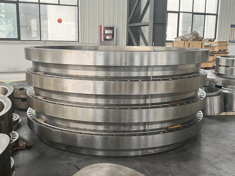
pressure vessel flange


Fasteners

The main requirements are as follows:

①The bolts, stud, and other fasteners used for flanges of low-temperature pressure vessels shall not use general ferrite commodity fasteners matched with nuts. General commodity nuts are allowed to be used, but the operating temperature should not be lower than -40 ℃;

② Recommend using elastic bolts and studs with a core diameter not exceeding 0.9 times the thread root diameter and no thread in the middle;

③ For ferritic steel vessels with a design temperature not lower than -100 ℃, ferritic steel fasteners (studs, bolts, nuts, washers) should be used. For austenitic steel vessels with a design temperature lower than -100 ℃, austenitic steel fasteners should be used;

④ A2 grade austenitic steel commercial fasteners in accordance with GB 3098.6 "Mechanical Properties of Fasteners - Stainless Steel Bolts, Screws, and Studs" can be used in low-temperature pressure vessels not lower than -196 ℃;

⑤ For stress reducing conditions, when the adjusted impact test temperature is equal to or higher than -20 ℃, general ferrite commodity fasteners can be used.

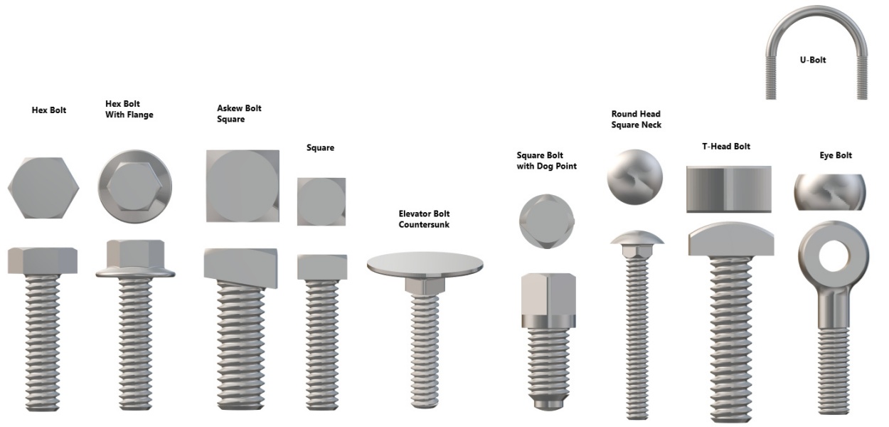
bolt stud nut


Sealing gasket

The commonly used sealing gaskets for low-temperature pressure vessels include gaskets made of metal materials (including semi metal gaskets) and non-metallic materials. The conditions and requirements are as follows.

① Metal materials used for sealing gaskets with temperatures below -40 ℃ should be austenitic stainless steel, copper, aluminum, and other metal materials that have no obvious transformation characteristics at low temperatures, including the metal strip of spiral wound gaskets, the shell of metal wrapped gaskets, and hollow or solid metal gaskets.

② Non metallic sealing gaskets should be made of materials that exhibit good elasticity at low temperatures, such as asbestos, flexible (expanded) graphite, polytetrafluoroethylene, etc. The usage conditions are as follows:

The flange sealing gasket with a temperature not lower than -40 ℃ and a pressure not higher than 2.5MPa is allowed to use high-quality asbestos rubber sheets, asbestos free rubber sheets, flexible (expanded) graphite sheets, polyethylene sheets, etc; High quality asbestos rubber sheets soaked in paraffin are allowed for flange gaskets with a temperature not lower than -120 ℃ and a pressure not higher than 1.6MPa.

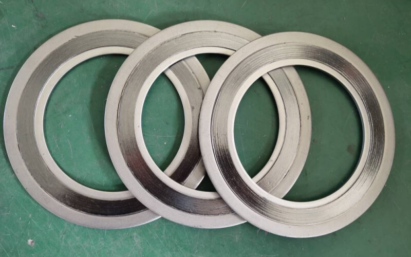
spiral wound gasket


Welding

The main requirements are as follows.

① For A B. All C-class welds should adopt a fully penetrated structure. For Class D welds, except for the welding between the flange and the container wall, the welding between small diameter nozzles (DN ≤ 50mm) and thicker heads or cover plates, and the connection between pipe joints with internal threads and the container wall, which can be in accordance with the relevant provisions of HG 20582, full penetration structures should also be used.

② Before welding low-temperature pressure vessels, welding process evaluation should be carried out, with a focus on the low-temperature Charpy (V-notch) impact test of the weld seam and heat affected zone. The qualification index should be determined according to the requirements of the base material and should not be lower than the performance of the base material.

③ During the welding process, the welding wire energy should be strictly controlled within the range specified in the process evaluation. It is advisable to choose a smaller welding wire energy for multi pass welding.

④ The butt weld must be fully welded, and the excess height of the weld should be minimized as much as possible, not exceeding 10% of the thickness of the welded part, and not exceeding 3mm. The fillet weld should be smooth and not allowed to protrude outward. The surface of the weld seam should not have defects such as cracks, pores, and undercuts, and there should be no sharp shape changes. All transitions should be smooth.

⑤ Arc ignition is not allowed in non welding areas. Arc ignition should be carried out using arc plates or within the groove.

⑥ Welding attachments, fixtures, braces, etc. must use the same welding materials and welding processes as the shell material, and be welded by qualified formal welders. The length of the weld bead must not be less than 50mm.

⑦ Surface damage to containers caused by mechanical processing, welding, or assembly, such as scratches, welding scars, arc pits, and other defects, should be repaired and ground. The wall thickness after grinding shall not be less than the calculated thickness of the container plus corrosion allowance, and the grinding depth shall not exceed 5% of the nominal thickness of the container and shall not exceed 2mm.

⑧ Discontinuous or spot welded joints are not allowed.


Wuxi Changrun has provided high-quality tube sheets, nozzles, flanges, and customized forgings for heat exchangers, boilers, pressure vessels, etc. to many well-known petrochemical enterprises at home and abroad. Our customers include PetroChina, Sinopec, Chevron, Bayer, Shell, BASF, etc. Send your drawings to sales@wuxichangrun.com We will provide you with the best quotation and the highest quality products.
Growing Demand for Sustainable Cables Drives Innovation in the Cable

In recent news, cable industry is experiencing a significant shift toward sustainable practices and eco-friendly solutions. With increasing awareness about environmental impact, both and businesses are prioritizing selection and purchase of environmentally friendly cables.


Major players in the cable industry are investing in research and development to introduce innovative solutions, such as rubber sheathed cables with enhanced sustainability features. These cables are designed to minimize environmental harm while maintaining optimal performance.


Renewable materials and recyclable components are being incorporated into the manufacturing process of rubber sheathed cables. This ensures reduced carbon footprint and promotes waste reduction throughout the lifecycle of the cables.


Furthermore, manufacturers are adopting energy-efficient production techniques and implementing stringent quality control measures to meet global standards for sustainability. These efforts contribute to the overall reduction of greenhouse gas emissions and resource consumption.


The growing demand for sustainable cables reflects the industry's commitment to a greener future. Consumers and businesses are increasingly recognizing the importance of making environmentally responsible choices in their purchasing decisions.


As the cable industry continues to prioritize sustainability and invest in eco-friendly technologies, the availability of high-quality rubber sheathed cables with superior performance and reduced environmental impact is set to increase. This trend positively impacts the industry and aligns with global efforts towards a more sustainable and greener future.


In conclusion, the cable industry is witnessing a transformative shift towards sustainability, with rubber sheathed cables at the forefront of this change. The integration of eco-friendly materials, energy-efficient production processes, and adherence to global standards highlights the industry's dedication to minimizing environmental impact. This news underscores the importance of making conscious decisions when selecting and purchasing cables, as we work together to embrace a sustainable future.

Growing Demand for Sustainable Cables Drives Innovation in the Cable

mingguan cable wire


The Growing Trend of Low Smoke Zero Halogen (LSZH) Cables in the Cable Industry

In recent years, the demand for safety and environmental consciousness has driven significant advancements in technology. One notable is the increasing popularity of Low Smoke Zero Halogen (LSZH) cables. These cables have gained widespread recognition due to their improved fire safety characteristics and reduced environmental impact. This blog explores the evolving trends and benefits of LSZH cables, making it a valuable topic for Google indexing.


1. Fire Safety Enhancement:

LSZH cables are designed to emit low levels of smoke and toxic gases when exposed to fire. Compared to traditional cables, LSZH cables significantly reduce the risk of smoke inhalation, increasing the chances of safe evacuation during emergencies. Governments and regulatory bodies are increasingly mandating the use of LSZH cables in public buildings, transportation systems, and other critical infrastructure.


2. Environmentally Friendly:

LSZH cables are manufactured using materials that avoid or minimize the release of hazardous halogens, such as chlorine and fluorine, during combustion. This makes them more environmentally friendly compared to PVC or other halogenated cables. As sustainability becomes a key focus globally, the adoption of LSZH cables is helping organizations reduce their carbon footprint and meet green certification requirements.


3. Broad Application Scope:

LSZH cables find applications in various industries, including telecommunications, automotive, aerospace, and marine. As connectivity becomes an integral part of our daily lives, the demand for LSZH cables in data centers, high-speed networks, and telecommunications infrastructure is rapidly increasing. Their ability to resist fire and minimize damage in critical situations makes them an ideal choice for dependable and secure connectivity.


4. Technological Advancements:

Continual research and development in cable engineering has led to notable advancements in LSZH cables. Innovations in flame retardant compounds, conductor materials, and insulation techniques have resulted in improved performance and durability. LSZH cables now offer better signal integrity, higher data transfer speeds, and increased resistance to mechanical stress, ensuring reliable performance in demanding environments.


Conclusion:

The growing demand for safety and sustainability solutions has propelled the popularity of LSZH cables in the cable industry. Their inherent fire safety characteristics, environmental benefits, and technological advancements make them a preferred choice for many applications. As this trend continues to evolve, it is crucial for consumers and industry professionals to stay informed about the latest developments in LSZH cable technology.


By providing valuable insights into the development and benefits of LSZH cables, this blog aims to facilitate knowledge sharing and contribute to a safer and greener future for the cable industry.

low halogen cablelow halogen cable


Waste copper wire and cable processing technology

Mechanical separation method

1) Drum peeling machine processing method. This method is suitable for processing waste wires and cables of the same diameter. This equipment already exists in our country. The Wolverhampton factory in the UK uses this kind of equipment to strip waste wires and cables, and the results are very good.

A. Copper and plastic in waste wires and cables can be comprehensively recycled, with a high level of comprehensive utilization;

C. The process is simple and easy to mechanize and automate;

2) Cutting type peeling machine processing method. This method is suitable for processing thick cables and wires, and a factory in Xiangfan, my country has been able to produce this equipment.


Low temperature freezing method

The cryogenic freezing method is suitable for processing wires and cables of various specifications. The waste wires and cables are first frozen to make the insulation layer brittle, and then crushed by shock to separate the insulation layer from the copper wires.


Chemical peeling method

This method uses an organic solvent to dissolve the insulation layer of the waste wire to achieve the purpose of separating the copper wire and the insulation layer. The advantage of this method is that it can obtain high-quality copper wire, but the disadvantage is that it is difficult to process the solution and the price of the solvent is high. The development direction of this technology is to research a cheap, practical and effective solvent; recommended product: control cable


Thermal decomposition method

The waste wires and cables are first sheared, and then added to the pyrolysis chamber for pyrolysis by the transport feeder. The pyrolyzed copper wires are sent to the outlet sealing pool by the grate conveyor, and then loaded into the product collector. The copper wires It can be used as raw material for producing refined copper. The gas produced by pyrolysis is sent to the afterburning chamber to burn the combustible substances in it, and then sent to the reactor to absorb the chlorine gas with calcium oxide and then discharged. The generated calcium chloride can be used as a building material.


Fire Rated Power Cable

Low   Smoke Fire   Resistant Cable

What is the main difference between control cables and computer cables?

The control electrical system is suitable for polyoxyethylene insulated and polyethylene sheathed control electrical systems used in industrial and mining enterprises, energy transportation departments, and for control and maintenance lines with AC rated voltages below 450/750 volts. Extra voltage: U0/ is 450/750v. Computer cables are suitable for computers and automated power-saving systems with rated voltages of 500v and below that require high anti-scan components. The insulation of the electric ground wire flower adopts K-type Class B low-density and E-burning with anti-oxidation function. Polyethylene has high insulation resistance, good deformed voltage, small dielectric impurity and little influence on dielectric loss, temperature and frequency. It can not only meet the requirements of transmission performance, but also ensure the service life of the cable.


In order to reduce mutual crosstalk and internal interference between circuits, the electrical system adopts a shielded structure. The shielding requirements of the electrical system are adopted according to different situations: continuous combined screen, total shielding of the electrical system composed of lines, total shielding after the combined shielding of the textile and other methods. There are three types of shielding materials: round copper wire, copper tape, aluminum tape, and seat material composite tape. The shielding pair and the shielding pair have good insulation properties, so if a potential difference occurs between the shielding pairs during use, the signal transmission quality will not be affected. The temporary service temperatures of conductor wires are 70°C and 105°C, and the normal laying temperature should not be lower than 0°C.


1. The insulation levels of the two are different. In absolute terms, the insulation level of control cables is slightly higher. Control cable insulation is generally 450/750V.


2. Computer cables relatively emphasize the shielding effect and have stronger anti-interference performance. Most of them adopt the method of partial shielding + total shielding.


3. Control cables have higher machine strength and tensile strength than computer cables, especially those with steel armor. Suitable for indoor digital installation or even underground installation. The computer electrical system is slightly weaker in strength and not tensile-resistant, and is generally only laid outside the substation or cabinet room.


Many manufacturers don't know what's going on. They use the standards of control electronics to manufacture communication systems. Not only do the produced electronics look stupid, but they can't be matched with communication parameters! The industrial automation system is developing rapidly, and computer electronics designed in the past are The system cannot meet the requirements! Nowadays, the industrial fieldbus with R5485/RS422 interface has gradually replaced the traditional dashboard-type control system. It is not only complex in structure, but also easy to maintain and facilitate networking.


There are essential differences between control electrical systems and computer electrical systems. When purchasing this type of electrical system, you should ask the customer service staff clearly to prevent problems.

computer cable connectors

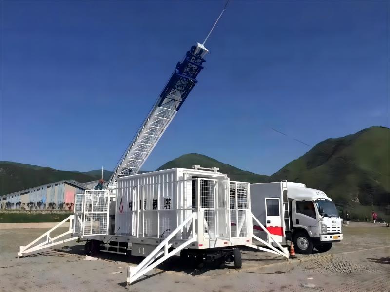
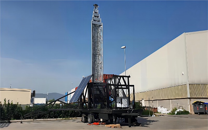
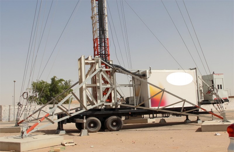
The Technical Specifications of A Typical Cell on Wheels Unit

The technical specifications of a typical Cell on Wheels (COW) unit can vary based on the specific equipment and configuration used by different cellular service providers and manufacturers. However, here are some common technical specifications that you might find in a typical Cell on Wheels unit:

cow tower telecom

1. Antennas:

   - Multiple high-gain directional antennas for transmitting and receiving cellular signals.

   - Antenna types can include omni-directional or sector antennas, depending on coverage requirements.


2. Mast:

   - Telescoping mast for raising antennas to an elevated height for broader coverage.

   - Adjustable mast height for optimizing signal propagation based on terrain and surroundings.


3. Radio Equipment:

   - Base transceiver station (BTS) or radio access network (RAN) equipment for connecting to the core network.

   - Multiple radio units supporting different frequency bands (e.g., LTE, 5G, etc.) for providing cellular service.


4. Backhaul Connectivity:

   - Fiber optic cables, microwave links, or satellite connections for backhaul to the core network.

   - High-speed data connections to ensure reliable communication between the COW and the network.


5. Power Supply:

   - Generators or battery backup systems to provide power to the COW unit.

   - Power distribution units for managing and distributing electrical power to various components.

cell on wheels manufacturers

6. Control and Monitoring Systems:

   - Remote monitoring and management systems for real-time performance monitoring.

   - Control interfaces for adjusting settings, optimizing coverage, and troubleshooting issues.


7. Environmental Protection:

   - Weatherproof enclosures and equipment to protect against environmental elements.

   - Climate control systems for temperature regulation in extreme weather conditions.


8. Network Compatibility:

   - Support for multiple cellular network technologies such as GSM, CDMA, LTE, and 5G.

   - Compatibility with different frequency bands to ensure seamless integration with existing network infrastructure.


9. Capacity and Throughput:

   - Capacity planning for handling a specific number of concurrent users and data traffic.

   - Throughput capabilities to support high-speed data services and multimedia applications.


10. Mobility and Transportability:

    - Mounted on a mobile platform such as a truck, trailer, or container for easy transportation.

    - Quick deployment and setup features for rapid deployment in emergency situations or temporary events.

mobile cell on wheels

These specifications can vary depending on the specific requirements of the deployment scenario, the cellular network technology being used, and the service provider's equipment choices. However, these are some common technical features you might find in a typical Cell on Wheels unit.


Learn more at www.alttower.com


Contact Us


telecom tower supplier


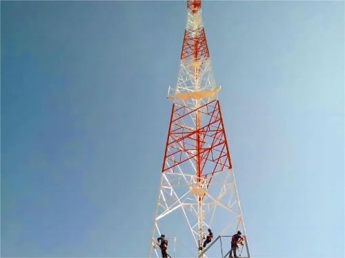
The Typical Height Ranges for Angular Steel Telecom Towers

Angular steel telecom towers come in various heights to meet the needs of different telecommunication applications. The height of a telecom tower is determined by factors such as coverage requirements, terrain, antenna type, and regulatory guidelines. Here are the typical height ranges for angular steel telecom towers:

angular steel telecom tower

1. Low-Height Towers:

   - Height Range: 30-60 feet (9-18 meters)

   - Use: Low-height towers are commonly used in urban and suburban areas where moderate coverage and capacity are required. They are suitable for mounting antennas for local coverage.


2. Medium-Height Towers:

   - Height Range: 60-200 feet (18-61 meters)

   - Use: Medium-height towers are often used in both urban and rural areas to provide broader coverage and capacity. They are suitable for mounting antennas for wider area coverage.

angular tower telecom

3. High-Height Towers:

   - Height Range: 200-500 feet (61-152 meters)

   - Use: High-height towers are used in areas that require extensive coverage, such as remote or hilly terrain. They are suitable for mounting antennas to cover large geographic areas.


4. Very High Towers:

   - Height Range: Above 500 feet (152 meters)

   - Use: Very high towers are rare and are typically used in extreme cases where exceptional coverage is required, such as in mountainous regions or for long-distance transmission.


The height of a telecom tower is carefully chosen to optimize signal coverage, line of sight, and network performance while considering factors like signal propagation, interference, and regulatory restrictions. The height range of a tower will vary based on the specific needs of the telecommunication network it serves.


It's important to note that these height ranges are approximate and can vary based on specific requirements and regional regulations. Additionally, taller towers typically require additional structural support, such as guy wires, to ensure stability and safety.


Qingdao Altai Tower Co., Ltd
Website: www.alttower.com
No.61 Haier Rd, Qingdao, China
Tel: +86 176 6762 1232
E-mail: attower88@gmail.com
Whatsapp: +852 6266 7210